How To Note Flatness Sheet Metal Drawings
Gd T Tips Free State

Quiz Question 8 Geo Tolerances Answers Technical Drawing Engineering Design Geometric Tolerancing

Quiz Question 8 Geo Tolerances Answers Technical Drawing Engineering Design Geometric Tolerancing

Wallet Sized Gd T Symbol Reference Card Omnia Mfg Engineering Symbols Geometric Tolerancing Mechanical Engineering Design

Eliminate Your Fears And Doubts About Mechanical Engineering Drawing Symbols Engineering Symbols Mechanical Engineering Design Mechanical Design

Engineering Drawings Gd T For The Quality Engineer Mechanical Engineering Design Mechanical Engineering Engineering Symbols
Bend tags associate rows in a bend table with the view geometry.
How to note flatness sheet metal drawings. I am apply my dimensions carefully so that they are unambiguous. Perfect flatness is when all points of a surface lie in the same plane. Although notes on each drawing will differ the first note on all sheet metal drawings that contain bends should be as follows. Minimum bend reliefs allowed.
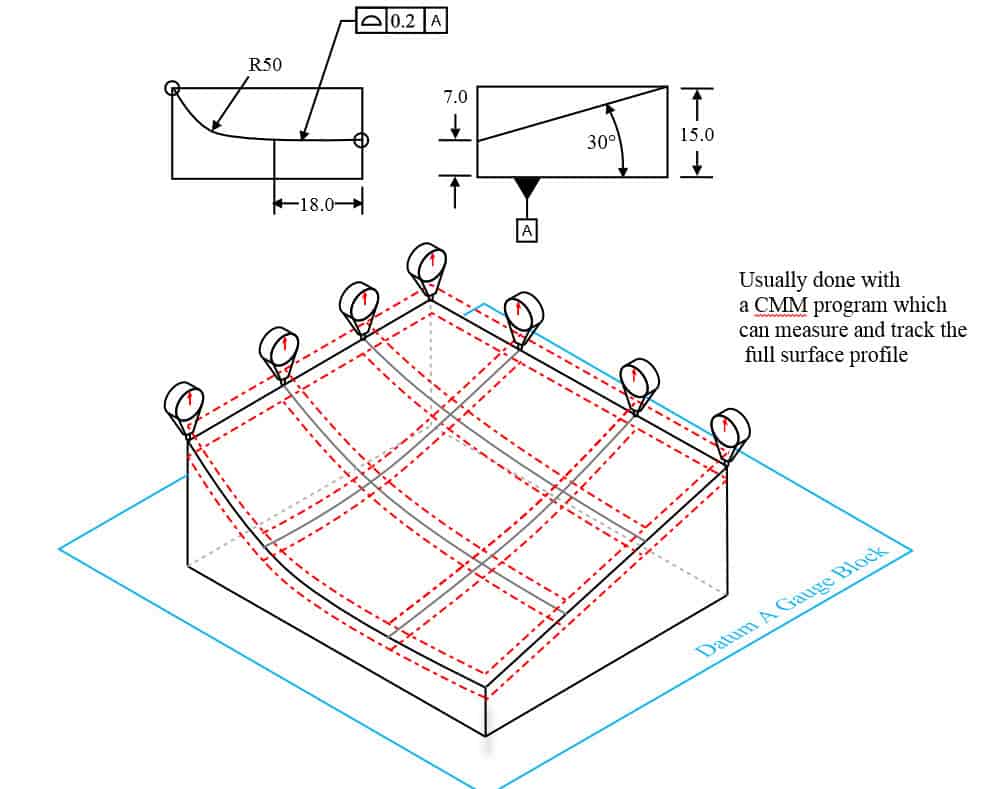
The boxed symbols can be read this surface must lie between two parallel planes spaced 0 2 apart in all views the right figure shows a possible actual part condition. Toggling the visibility of bend lines. I systematrically specify bend radii on my drawings and i include details showing what the bend corners look like before bending. I want stress relief radii.
Toggling the visibility of sheet metal bend notes. For door panels front panels interior panels and racks see document 10 1006 for information on adding a note regarding the implementation eps 121. Sheet metal bend line notes. To control the bow try using straightness applied to your sheet metal gauge thickness feature of size.
After you insert the bend table in the drawing bend tags are added to the selected drawing view automatically. Note that the flatness tolerance must be less than the size tolerance associated with the surface. Bend tags are formatted by the dimension style and do not have a leader by default. It is a common symbol that references how flat a surface is regardless of any other datums or features.
The flatness control c defines how much a surface on a real part may vary from the ideal flat plane. Flatness is a form control. It comes in useful if a feature is to be defined on a drawing that needs to be uniformly flat without tightening any other dimensions on the drawing. Dimensions given on a flat pattern are affected by several bending factors like k factor and bend radius during the 3d modeling stage.
I don t put any standard notes on my sheet metal drawings. Unless you need the part to have a flatness that is better than the sheet metal gauge tolerance. The flatness control c defines how much a part s surface may deviate from its perfect flat form. I have read up on and taken a course on the asme y14 5m 1994.
Creating drawings of flat patterns. No mmc or lmc applicable. Toggling the visibility of bend region lines. To put a flatness on sheet metal part will be hard to control because of the stock sheet metal gauge size tolerances are relatively nice and tight.
The flat pattern drawing doesn t always list these factors. Gd t flatness is very straight forward. Yes new in 2009 drawing callout. Flat pattern drawing views can display bend line notes or bend tables.

Gd T Symbols Mechanical Engineering Design Mechanical Design Engineering Symbols

Geometric Tolerances Investment Castings To Precise Geometric Tolerances Milwaukee Precision Geometric Tolerancing Geometric Mechanical Engineering Design
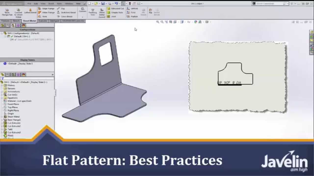
Solidworks Sheet Metal Tutorial Flat Pattern Best Practices Youtube
Flatness Gd T Basics

Following Dfm Guidelines For Working With Sheet Metal Machine Design

Storyboard Background Tips From Spongebob Artist Sherm Cohen In 2020 Comic Tutorial Spongebob Drawings Comic Drawing

Coining And Embossing Around Flared Holes Improves A Part S Strength And Its Ability To Maintain Its Fla Sheet Metal Mechanical Engineering Design Metal Design
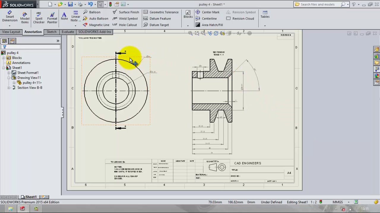
Drafting And Add Gd T In Solidworks Tutorial Youtube

Csvm Construction Log 5 Block Shaping Blocks Violin

Pin On Technical Drawing
Https Docs Plm Automation Siemens Com Data Services Resources Se 109 Se Help En Us Selfpacedext Pdf Mt01419 Pdf
Https Www Qualitymag Com Ext Resources Files Gdt Gdt Resource Updated Pdf

Casing Windows Jlc Online Molding Millwork And Trim Carpentry Windows Building Windows Molding And Millwork Window Installation

Gutter Maintenance Everything Gutter Box Gutter Parapet Butterfly Roof
Profile Of A Surface Gd T Basics

Parallelism Gd T Basics

Dallas Galvalume 24 Gauge Metal Roofing Systems Metal Roof Metal Roofing Systems Zinc Roof
Catia Gd T Tutorial 9 Youtube
Https Encrypted Tbn0 Gstatic Com Images Q Tbn 3aand9gcq53f8tkskz2ngohfg4jijc6vbdqj86 M0 Ftxbbalurm2eh8v5 Usqp Cau

Csvm Construction Log 5 Block Shaping Violin Design Chicago School Blocks

Wall Covering Steel Panels Stainless Steel Panels Interior Cladding Wall Cladding Designs

New Manufacturing Blueprint Symbols Diagram Wiringdiagram Diagramming Diagramm Visuals Visualisation G Blueprint Symbols Geometric Tolerancing Geometric

New To Creo 4 0 Creating Editing Geometric Tolerances Gtols Youtube
3 D Cad Productivity Reliability And Responsiveness
Metal Stamping And Die Design Blanking Machinemfg
Http Web Mit Edu 2 810 Www Files Lectures 2015 Lectures Lec6 Sheet Metal Forming 2015 Pdf

Blue Print Reading Intro To Gd T Youtube Geometric Tolerancing Blue Print Print

Pin On Planos

Aluminum Composite Panel Fachada De Acm Revestimento Fachada Tipos De Dobras
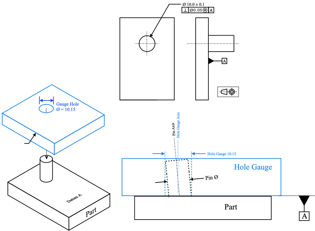
Maximum Material Condition Mmc Gd T Basics
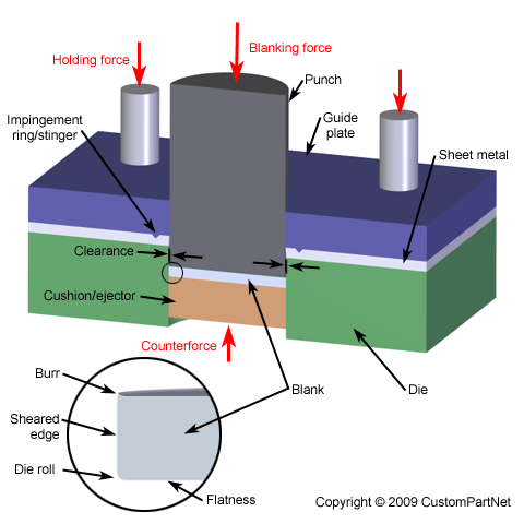
Sheet Metal Cutting Shearing
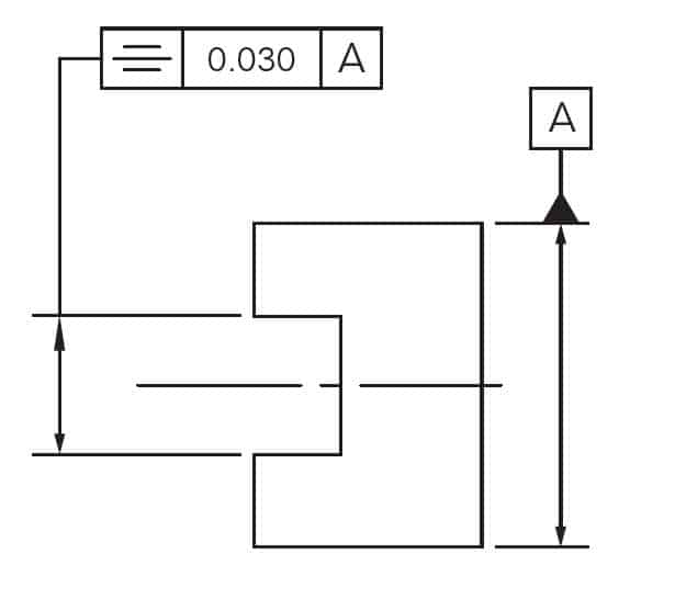
Symmetry Gd T Basics

Pin On Basu
Multistage Drawing Process Of Cylindrical Cups Based On Numerical Simulation Analysis And Experimental Study Springerlink
Flatness All You Need To Know About Gd T Flatness

Radius Gauges Fillet Gauges How To Use Fillet Gauges Extrudesign Radii Fillet Basic Concepts

Straightness Gd T Basics

Bend Drawing Tips Cad Help Guide Emachineshop

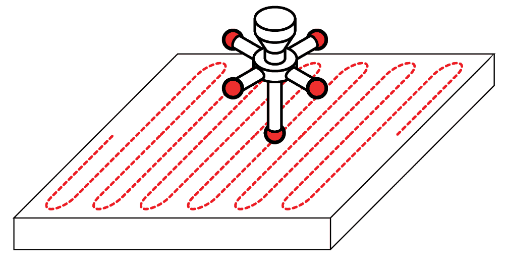
How To Control The Warping Of Parts In Thin Sheet Metal Fabricating And Metalworking

Art Work Made On My Ba Fine Art Degree Between 2006 2008 Natalie Parsley Bunch Of Keys 2008 Oil Gcse Art Sketchbook Mechanical Art Art Sketchbook

Press Brake Dies Toolings The Ultimate Guide Machinemfg
Show Flattened Pattern In Draft

